VRBRAIN 5
VRBRAIN5 now supports up to 2 compasses.
The first compass is on the board.
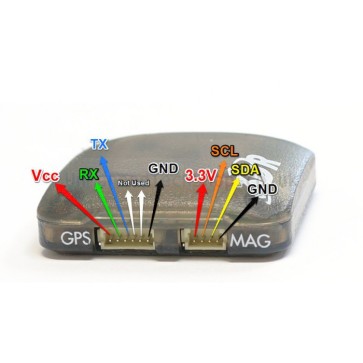
If you re using the VRX GPS or the 3DR GPS you can connect the external Compass to the SDA and SCL connectors near the GPS connector as shown in below figure:
You can however use the secondary I²C to connect another External compass or any other I²C peripheral like an external led or sonar ect,
Remeber that if you use another HMC5883L or HMC5983 compass you need to disable internal compass by removing the Jumper placed on the side of the board like shown in figure
VRBRAIN 4.x
External compass.
With latest code you can attach an external compass to the VRBRAIN.
Unfortunately at the time the VRBRAIN was designed, external compasses were not so popular and the HMC5883L can only have one address, so two compasses on the same I2C bus would conflict and block the bus.
So there are two methods to achieve this:
1. Cut the SDA trace on the board or desolder the compass. (NOT RECOMMENDED)
This is the method you would prefer if you have high desoldering skills or if your bird is an OCTO or OCTO-QUAD because the external I2C port is fisically shared with motor output 7 and 8 and you cannot use OCTO configurationa and External Mag toghether.
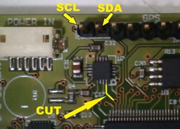
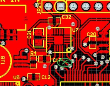
Once you cut the trace or desolder the chip you can connect the External mag to the internal I2C as shown on below figure.
This is where you have to cut the trace and where you need to connect the external compass:
Noter that you don’t need to download a special firmware, just use the standard internal compass firmware.
2. Attach SCL and SDA to output 7 & 8, add two resistors and upload the appropriate firmware.
This is the preferred method if you fly QUAD HEXA TRI etc but it is not compatible with OCTO or OCTO-QUAD.
So first step is to download the VRBRAIN_xxx_EXT-COMP firmware.
Note the suffix _EXT-COMP.
Then make up a cable so you can attach the compass on the 7th and 8th port of the OUTPUT rail. You need only the SDA and SCL cables if you are using the 3DR compass with Mag included.
Because the external mag on the 3DR GPS has no resistors (it should….) you need to add two 5V 2k2Ω resistors at one of the two ends of the connection cable one for SDA and one for SCL.
Attach one end of the resistor to the cable and the other to the +5V
GND and +5V are already feeded to the compas via the GPS.
Attach SCL to Output 7 and SDA to output 8.
If you attach the SDA and SDL to the relative ports, and the order is correct, the the FW will auto detect the compass and boot normally, otherwise if you see the Yellow LED on the board constantly ON and not blinking, it means you have the wrong order. Swap the cables and reboot the VRBRAIN.
Configuring Mission Planner
Once everything is connected correctly, you have to configure your Board with the new compass.
To do this follow these instructions:
a. Open Mission Planner and connect to the board
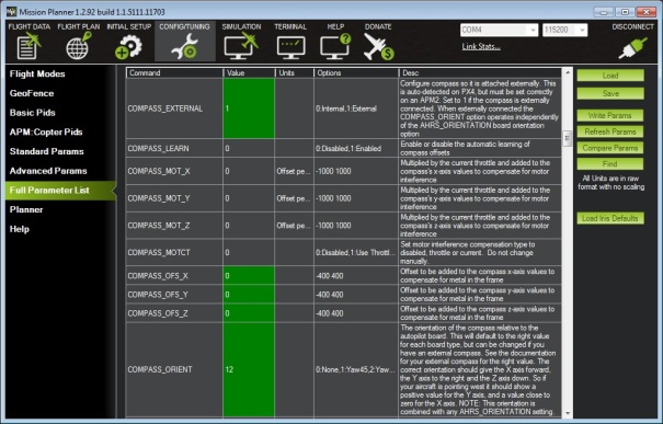
b. Go in Tab CONFIGTUNING and then in Full Parameter List
c. Locate the Var: COMPASS_EXTERNAL an set the value to 1
d. locate the Var: COMPASS_ORIENTATION and set the value to 12 (Pitch 180)
e. locate and set to 0 (zero) the following parameters:
| COMPASS_OFS_X | 0 |
| COMPASS_OFS_Y | 0 |
| COMPASS_OFS_Z | 0 |
This is to ensure the values of the old calibration gets erased and you don’t fly with bad calibration.
f. Write parameters to EEPROM clicking the Write Params button.
All this assuming you have a 3DR compass and you set up the compass with the arrow pointing forward.
g. Rebbot the board and verify that the compass is pointing in a corret direction.
h. Recalibrate the compass far away from magnetic interference.
i. Fly and enjoy the external compass!


The method number 1, that is not recommended, shows the track to be cut, but do not specify on which pins you have to connect the external compass after cutting.
Thank you for pointing me out this.
I have corrected the image and show the SDA and SCL connectors.
Emile
Ciao emile ,
se volessi mettere solo il magnetometro della 3dr HMC5883L https://store.3drobotics.com/products/hmc5883l-triple-axis-magnetometer, devo sempre aggiungere le resistenze ?
Come dovrei effettuare i collegamenti?
Grazie Alfio
Complimenti per il lavoro svolto 🙂
No in quel caso no. Le resistenze sono già presenti sulla board.
I dont understand where to attach the resistors?
in the SCL or SDA? or both,? on the photo its look like the scl and sdl are conected togther.
Thnx
You should connect the resistors on both SDA and SCL. they have to be connected to the 5V on one end and the signal on the other end.
Sorry for late reply, but the email wen into spam….
Emile
Sorry i dont understand.
From the 3DR 2 cable from the compass. 1 for SDA to Vrbrain 7 and 1 SCL to Vrbrain 8
Is the resistor is in serial to each cable?
thanks Amit
@amit
The resistors must not be placed in series with the signals SDA / SCL, but between SDA / SCL and the center pin at 5V.
Ciao a tutti, Ho appena installato VRbrain sul mio Quad, e non riesco a far funzionare la modalità Loiter: appena la inserisco il Quad inizia a scivolare su un lato e prende sempre più velocità. Ho verificato la correttezza dei collegamenti con il GPS Ublox, ricaricato il FW *.16 per magnetometro esterno, rifatto la calibrazione bussola e verificato la declinazione. Avete altri suggerimenti?
Il punto 2 “Attach SDA and SCL to output 7 & 8, add two resistors and upload the appropriate firmware.” può trarre in inganno se si fa la naturale associazione SDA=pin7 ed SCL=pin8.
La giusta connessione è SCL=pin7, SDA=pin8.
Thanks corrected!