Copter 3.3

Copter 3.3 is released on Mission Planner and our Dropbox

We decided to keep it in beta for now to keep still available version 3.2.1 for anyone prefer and until the release of the next beta.

Now there are new drivers available from NuttX OS and started from startup script:

  • Eagle Tree Airspeed MicroSensor V3 – I2C bus
    • Only on I2C external bus for all boards (this bus is already used for external magnetometer and is available on all VR boards).
  • MEAS Digital Pressure Modules MS4525DO – I2C bus
    • Only on I2C external bus for all boards (this bus is already used for external magnetometer and is available on all VR boards).
  • Maxbotix sonar range finder MB12XX – I2C bus
    • Only on I2C external bus for all boards (this bus is already used for external magnetometer and is available on all VR boards).
  • RGB LED controller (TCA62724FMG) – I2C bus
    • Only on I2C external bus for all boards (this bus is already used for external magnetometer and is available on all VR boards)
  • PulsedLight Lidar-Lite V2 range finder – I2C bus
    • Only on I2C external bus for VR Brain 4.5, VR Brain 5.1, VR Micro Brain 5.1 and VR Micro Brain 5.2.
    • Both on I2C external bus and I2C external extra bus (DF13 connector under SERIAL2) for VR Brain 5.2. It’s possible to connect the sensor on one of these two buses.
  • TeraRanger One range finder – I2C bus
    • Only on I2C external bus for VR Brain 4.5, VR Brain 5.1, VR Micro Brain 5.1 and VR Micro Brain 5.2.
    • Both on I2C external bus and I2C external extra bus (DF13 connector under SERIAL2) for VR Brain 5.2. It’s possible to connect the sensor on one of these two buses.
  • OpticalFlow – I2C bus
    • Only on I2C external bus for VR Brain 4.5, VR Brain 5.1, VR Micro Brain 5.1 and VR Micro Brain 5.2.
    • Both on I2C external bus and I2C external extra bus (DF13 connector under SERIAL2) for VR Brain 5.2. It’s possible to connect the sensor on one of these two buses.
  • PulsedLight Lidar-Lite V1 range finder – PWM
    • This sensor has also an I2C bus available but there is a bug into its firmware and it is not safe. We recommend using this sensor only in PWM mode.
    • Available only for VR Brain 5.1, VR Brain 5.2 and VR Micro Brain 5.1.
    • This sensor needs a PWM input (pin 5 of inputs connector) and a Digital Output (reset of the sensor – pin 6 of inputs connector).
Posted in Copter

Plane 3.4.0

Plane 3.4.0 is released on Mission Planner and our Dropbox

Now there are new drivers available from NuttX OS and started from startup script:

  • Eagle Tree Airspeed MicroSensor V3 – I2C bus
    • Only on I2C external bus for all boards (this bus is already used for external magnetometer and is available on all VR boards).
  • MEAS Digital Pressure Modules MS4525DO – I2C bus
    • Only on I2C external bus for all boards (this bus is already used for external magnetometer and is available on all VR boards).
  • Maxbotix sonar range finder MB12XX – I2C bus
    • Only on I2C external bus for all boards (this bus is already used for external magnetometer and is available on all VR boards).
  • RGB LED controller (TCA62724FMG) – I2C bus
    • Only on I2C external bus for all boards (this bus is already used for external magnetometer and is available on all VR boards).
  • PulsedLight Lidar-Lite V2 range finder – I2C bus
    • Only on I2C external bus for VR Brain 4.5, VR Brain 5.1, VR Micro Brain 5.1 and VR Micro Brain 5.2.
    • Both on I2C external bus and I2C external extra bus (DF13 connector under SERIAL2) for VR Brain 5.2. It’s possible to connect the sensor on one of these two buses.
  • TeraRanger One range finder – I2C bus
    • Only on I2C external bus for VR Brain 4.5, VR Brain 5.1, VR Micro Brain 5.1 and VR Micro Brain 5.2.
    • Both on I2C external bus and I2C external extra bus (DF13 connector under SERIAL2) for VR Brain 5.2. It’s possible to connect the sensor on one of these two buses.
  • OpticalFlow – I2C bus
    • Only on I2C external bus for VR Brain 4.5, VR Brain 5.1, VR Micro Brain 5.1 and VR Micro Brain 5.2.
    • Both on I2C external bus and I2C external extra bus (DF13 connector under SERIAL2) for VR Brain 5.2. It’s possible to connect the sensor on one of these two buses.
  • PulsedLight Lidar-Lite V1 range finder – PWM
    • This sensor has also an I2C bus available but there is a bug into its firmware and it is not safe. We recommend using this sensor only in PWM mode.
    • Available only for VR Brain 5.1, VR Brain 5.2 and VR Micro Brain 5.1.
    • This sensor needs a PWM input (pin 5 of inputs connector) and a Digital Output (reset of the sensor – pin 6 of inputs connector).
Posted in Plane

Rover 2.50 stable and 2.51 beta

Rover 2.50 stable and Rover 2.51 beta are released on Mission Planner and our Dropbox

Now there are new drivers available from NuttX OS and started from startup script:

  • Eagle Tree Airspeed MicroSensor V3 – I2C bus
    • Only on I2C external bus for all boards (this bus is already used for external magnetometer and is available on all VR boards).
  • MEAS Digital Pressure Modules MS4525DO – I2C bus
    • Only on I2C external bus for all boards (this bus is already used for external magnetometer and is available on all VR boards).
  • Maxbotix sonar range finder MB12XX – I2C bus
    • Only on I2C external bus for all boards (this bus is already used for external magnetometer and is available on all VR boards).
  • RGB LED controller (TCA62724FMG) – I2C bus
    • Only on I2C external bus for all boards (this bus is already used for external magnetometer and is available on all VR boards).
  • PulsedLight Lidar-Lite V2 range finder – I2C bus
    • Only on I2C external bus for VR Brain 4.5, VR Brain 5.1, VR Micro Brain 5.1 and VR Micro Brain 5.2.
    • Both on I2C external bus and I2C external extra bus (DF13 connector under SERIAL2) for VR Brain 5.2. It’s possible to connect the sensor on one of these two buses.
  • TeraRanger One range finder – I2C bus
    • Only on I2C external bus for VR Brain 4.5, VR Brain 5.1, VR Micro Brain 5.1 and VR Micro Brain 5.2
    • Both on I2C external bus and I2C external extra bus (DF13 connector under SERIAL2) for VR Brain 5.2. It’s possible to connect the sensor on one of these two buses.
  • OpticalFlow – I2C bus
    • Only on I2C external bus for VR Brain 4.5, VR Brain 5.1, VR Micro Brain 5.1 and VR Micro Brain 5.2.
    • Both on I2C external bus and I2C external extra bus (DF13 connector under SERIAL2) for VR Brain 5.2. It’s possible to connect the sensor on one of these two buses.
  • PulsedLight Lidar-Lite V1 range finder – PWM
    • This sensor has also an I2C bus available but there is a bug into its firmware and it is not safe. We recommend using this sensor only in PWM mode.
    • Available only for VR Brain 5.1, VR Brain 5.2 and VR Micro Brain 5.1.
    • This sensor needs a PWM input (pin 5 of inputs connector) and a Digital Output (reset of the sensor – pin 6 of inputs connector).
Posted in Rover

APMRover 2.48 released for all board

These are the main features released with APMRover 2.48:

  1. Serial Management: dynamic management of serial ports
  2. FrSky Telemetry for Taranis via S-Port: now is officially supported
  3. RGB onboard LED: new dvanced management
  4. External I2C RGB LED: it’s now possible to connect an external RGB LED on I2C bus (for all boards the same of the external Magnetometer)

ATTENTION: it is recommended to reset the parameters after uploading this version

Posted in Rover

ArduPlane 3.2.3 released for all boards

These are the main features released with ArduPilot 3.2.3:

  1. Serial Management: dynamic management of serial ports
  2. RGB onboard LED: new dvanced management
  3. External I2C RGB LED: it’s now possible to connect an external RGB LED on I2C bus (for all boards the same of the external Magnetometer)

ATTENTION: it is recommended to reset the parameters after uploading this version

Posted in Plane

ArduCopter 3.2.1 released for all boards

These are the main features released with ArduCopter 3.2.1:

  1. Serial Management: dynamic management of serial ports
  2. FrSky Telemetry for Taranis via S-Port: now is officially supported
  3. RGB onboard LED: new dvanced management
  4. External I2C RGB LED: it’s now possible to connect an external RGB LED on I2C bus (for all boards the same of the external Magnetometer)

ATTENTION: it is recommended to reset the parameters after uploading this version even if it comes from the Arducopter 3.2

1. Serial Management

On our boards, there are the following serial ports:

SERIAL0: this is always the USB serial port and it is possible to use it only with MAVLink protocol. Connected to a PC, it is useful to configure and monitor the board and to download the logs in a very fast and secure way.

For all each other port, in the list of parameters, there are two items for setting baud rate and protocol:

  • SERIALn_BAUD: With this parameter, it is possible to set the baud rate of the serial port. The possible values are: 1: 1200, 2: 2400, 4: 4800, 9: 9600, 19: 19200, 38: 38400, 57: 57600, 111: 111100, 115: 115200, 500: 500000, 921: 921600, 1500: 1500000
  • SERIALn_PROTOCOL: this is the protocol (or service) to use on the serial port. The possible values are:
    • 1: Primary GCS MAVLink. This is the first channel for telemetry via MAVLink to use with a communication channel (like as radio link) and GCS or similar
    • 2: Secondary GCS MAVLink. This is the second channel for telemetry via MAVLink to use with a communication channel (like as radio link) and GCS or similar. In the future, it will be possible to use this channel to bridge with another device that maycommunicate with theGCSwith the same
    • 3: FrSky D-Port Telemetry. This protocol is useful to send the telemetry to Taranis via D-Port of the FrSky D4R-II receiver.
    • 4: FrSky S-Port Telemetry. This protocol is useful to send the telemetry to Taranis via S-Port of the FrSky XnR (X4R, X6R and X8R) receiver. It is necessary to install some useful LUA script on the Taranis.
    • 5: Primary GPS. First GPS module
    • 6: Secondary GPS. Second GPS module
    • 7: Alexmos Gimbal Serial
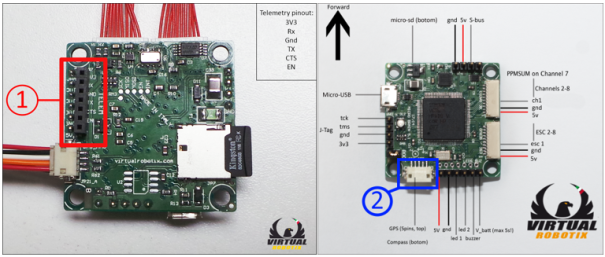
1.1 VR Brain 4.5

VRBrain-45_top-Serial

The default configuration is:

  • SERIAL1 (BAUD 57, PROTOCOL 1): this is the primary GCS MAVLink. With this configuration, this is the port to connect the radio link to communicate with GCS. It is possible to use this port for sending telemetry to Taranis setting the protocol 4 and connecting the appropriate inverter for S-Port
  • SERIAL2 (BAUD 38, PROTOCOL 5): this is the primary GPS module.

The possible scenarios are:

  • GCS Mavlink on SERIAL1 and Primary GPS on SERIAL2 (default setup)
  • S-Port Telemetry on SERIAL1 and Primary GPS on SERIAL2
    • SERIAL1_BAUD = 57 and SERIAL1_PROTOCOL = 4
  • Primary GPS on SERIAL1 and GCS Mavlink on SERIAL2
    • SERIAL1_BAUD = 38 and SERIAL1_PROTOCOL = 5
    • SERIAL2_BAUD = 57 and SERIAL2_PROTOCOL = 1
  • Primary GPS on SERIAL1 and S-Port Telemetry on SERIAL2
    • SERIAL1_BAUD = 38 and SERIAL1_PROTOCOL = 5
    • SERIAL2_BAUD = 57 and SERIAL2_PROTOCOL = 4

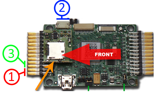
1.2 VR Micro Brain 5.1 and 5.2

vrubrain_serial

The default configuration is:

  • SERIAL1 (BAUD 57, PROTOCOL 1): this is the primary GCS MAVLink. With this configuration, this is the port to connect the radio link to communicate with GCS. It is possible to use this port for sending telemetry to Taranis setting the protocol 4 and connecting the appropriate inverter for S-Port
  • SERIAL2 (BAUD 38, PROTOCOL 5): this is the primary GPS module.

The possible scenarios are:

  • GCS Mavlink on SERIAL1 and Primary GPS on SERIAL2 (default setup)
  • S-Port Telemetry on SERIAL1 and Primary GPS on SERIAL2
    • SERIAL1_BAUD = 57 and SERIAL1_PROTOCOL = 4

1.3 VR Brain 5.1 and 5.2

vrbrain_serial

The default configuration is:

  • SERIAL1 (BAUD 57, PROTOCOL 1): this is the primary GCS MAVLink. With this configuration, this is the port to connect the radio link to communicate with GCS. It is possible to use this port for sending telemetry to Taranis setting the protocol 4 and connecting the appropriate inverter for S-Port
  • SERIAL2 (BAUD 57, PROTOCOL 2): this is the secondary GCS MAVLink. It is possible to use this port for sending telemetry via MAVLink to different devices or to send telemetry to Taranis setting the protocol 4 and connecting the appropriate inverter for S-Port
  • SERIAL3 (BAUD 38, PROTOCOL 5): this is the primary GPS module.

In this case, the scenarios are different depending on the configuration of the serial. We list below the most significant scenarios. These are only a few examples:

  • GCS Mavlink on SERIAL1 and Primary GPS on SERIAL3 (default setup). In this case, the SERIAL2 is not used.
  • GCS Mavlink on SERIAL1, S-Port Telemetry on SERIAL2 and Primary GPS on SERIAL3
    • SERIAL2_BAUD = 57 and SERIAL2_PROTOCOL = 4
  • GCS Mavlink on SERIAL1, Primary GPS on SERIAL2 and S-Port Telemetry on SERIAL3. This scenario is useful especially with VR Brain 5.2 because, with SERIAL2 there is a similar connector for the external I2C to use for magnetometer of GPS. In this case, it is possible to use the GPS module with the same connectors used with VR Micro Brain 5.1 and 5.2
    • SERIAL2_BAUD = 38 and SERIAL2_PROTOCOL = 5
    • SERIAL3_BAUD = 57 and SERIAL3_PROTOCOL = 4
  • GCS Mavlink on SERIAL1, Primary GPS on SERIAL2 and Secondary GPS on SERIAL3.
    • SERIAL2_BAUD = 38 and SERIAL2_PROTOCOL = 5 (or 6)
    • SERIAL3_BAUD = 38 and SERIAL3_PROTOCOL = 6 (or 5)

2. FrSky Telemetry for Taranis via S-Port

See this manual for:

  • How to build the serial inverter to connect to FrSky receiver’s S-Port
  • How to update OpenTX firmware of Taranis and to install the LUA scripts to show the telemetry on LCD

See the previous chapter instead for setting the serial: the value to set for FrSky Telemetry via S-Port becames 4.

3. Advanced Management of RGB on board LED

These are the states of RGB on board LED and their meaning:

  • Flashing red and blue: Initializing gyroscopes. !! Hold the vehicle still and level while it initializes the sensors.
  • Flashing blue: Disarmed, no GPS lock found
  • Solid blue: Armed with no GPS lock
  • Flashing green: Disarmed, GPS lock acquired (with quick double beep tone at time of disarming)
  • Solid green: Armed, GPS lock acquired (with single long tone at time of arming)
  • Double flashing yellow: Failing pre-arm checks
  • Single Flashing yellow: Radio failsafe activated
  • Single Flashing yellow: Battery failsafe activated
  • Flashing blue and yellow: GPS glitch or GPS failsafe activated
  • Flashing red and yellow: EKF or Inertial Nav failure
  • Flashing purple and yellow: Barometer glitch
Posted in Copter

Firmware 3.2 released for all boards!

Dear all, VirtualRobotix is proud to announce the release of the 3.2 APM:Copter firmware for all VRX boards.

Posted in Uncategorized

Micro SD card reader for VRBRAIN 4.5

Dear all, in the VirtualRobotix.it e-shop you will find an expansion board for your 4.5 board.

This will allow you to install 3.2 firmware with NuttX RTOSand enjoy Full logs on SD card, terrain following any many other upcoming features.

This card will plug directly into the white connector in the middle of the board.

Plug and Play!

http://www.virtualrobotix.it/index.php/en/shop/accessories/vr-brain-4-5-sd-card-expansion-detail

Posted in Uncategorized

New Firmware 3.2 in download section

Dear all, it’s been a while since last update, but things were going on, so we are finally proud to announce the new 3.2 firmware for all VRBRAIN 4.x users.

 
Last week, APM developers finally released the 3.2 version for APM:Copter.
This is a major release and sets a new milestone in the history of this firmware..
Because the new firmware is targeted to fast MCUs, it is now possible to appreciate all the goodies like EKF filter for navigation and stability, spline waypoints, smoother follow me and many security features.
 
This version is aimed for all VRBRAIN 4 and 4.5 boards that do not have an SD card reader.
 
For people using an SD card it is possible to install new firmware with NuttX operating system that will allow you to save logs on dataflash and use terrain data for future implementations.
To purchase an SD card expansion board you can follow this link, or build yourself one using this tutorial

These are the main release notes for this specific port:
  • Automatic external/internal compass recognition. No need to use a special firmware (not available for OCTA or OCTA-QUAD)
  • GPS port configurable via mission planner on 2 serial ports (internal connector or external connector near input rail). No need to upload a special firmware.
  • 8 PWM inputs, SBUS support with adapter cable, PPMSUM
  • Up to 12 outputs if using PPMSUM or SBUS
  • ALL automatic functions of the APM:Copter 3.2 (ROI, GUIDED,FOLLOW ME etc.)
  • EKF support. 
  • Logging on 2 Mbit high speed dataflash.
  • Future updates via mission planner
 
Known issues or not possible features:
  • Only one compass at a time (at the moment). You can either use the internal or external compass. You need to redo calibration and reconfiguration after compass change.
  • No multiple GPS supported (at the moment)
  • No multiple IMU supported
  • The use of external sensors such as OptFlow, Sonar, Airspeed etc. has not been tested.
  • No terrain following or infinite logs on SD card.
Please report any issues you may encounter in the install process or any question you may have on the new release.
 
Have fun and fly safe!

If you want to contribute or test latest revisions please follow the instructions on how to build and upload the code yourself.

For any special requests or to suggest improvements, please contact me at e.castelnuovo [at] virtualrobotix.com

Have fun and fly safe!

Emile

The VirtualRobotix Team

Posted in Uncategorized

Support for External compass on firmware 3.1

In the firmware download section, I have pushed a new firmware update to allow the use of an external compass on the VRBRAIN 4.0 or 4.5

The instructions on how to connect an external compass can be found here: Using an Eternal Compass

Be aware that you cannot connect an External compass without cutting a trace or disassembling the internal chip if you fly OCTO or OCTO_QUAD.

Because the secondary I2C port is shared with output 7 and 8, you will also loose Gimbal Control if you fly Hexa or Y6.

Please feel free to ask any questions if something is not totally clear.

Have fun and Fly safe!

Emile

The VirtualRobotix Team

Posted in Uncategorized
News